When the MPDU is passed down to the PHY layer, it is processed by the PHY Layer Convergence Procedure (PLCP) and receives a preamble and header, which depend on the specific type of PHY layer in use. The PLCP preamble contains a string of bits that enables a receiver to synchronise its demodulator to the incoming signal timing.
The preamble is terminated by a specific bit sequence that identifies the start of the header, which in turn informs the receiver of the type of modulation and coding scheme to be used to decode the upcoming data unit.
The assembled PLCP Protocol Data Unit (PPDU) is passed to the Physical Medium Dependent (PMD) sublayer, which transmits the PPDU over the physical medium, whether that is twisted-pair, fibre-optic cable, infra-red or radio. PHY layer technologies determine the maximum data rate that a network can achieve, since this layer defines the way the data stream is coded onto the physical transmission medium.
However, the MAC and PLCP headers, preambles and error checks, together with the idle periods associated with collision avoidance or backoff, mean that the PMD layer actually transmits many more bits than are passed down to the MAC SAP by the Data Link layer.
The next sections look at some of the PHY layer technologies applied in wired networks and briefly introduces the key features of wireless PHY technologies.
Physical Layer Technologies — Wired Networks
Most networks that use wireless technology will also have some associated wired networking elements, perhaps an Ethernet link to a wireless access point, a device-to-device FireWire or USB connection, or an ISDN based Internet connection.
Ethernet (IEEE 802.3)
The first of these, Ethernet, is a Data Link layer LAN technology first developed by Xerox and defined by the IEEE 802.3 standard. Ethernet uses Carrier Sense Multiple Access with Collision Detection (CSMA/CD), described above, as the media access control method. Ethernet variants are known as “A” Base-“B” networks, where “A” stands for the speed in Mbps and “B” identifies the type of physical medium used.
10 Base-T is the standard Ethernet, running at 10 Mbps and using an unshielded twisted-pair copper wire (UTP), with a maximum distance of 500 metres between a device and the nearest hub or repeater.
The constant demand for increasing network speed has meant that faster varieties of Ethernet have been progressively developed. 100 Base-T, or Fast Ethernet operates at 100 Mbps and is compatible with 10 Base-T standard Ethernet as it uses the same twisted-pair cabling and CSMA/CD method.
The trade-off is with distance between repeaters, a maximum of 205 metres being achievable for 100 Base-T. Fast Ethernet can also use other types of wiring — 100 Base-TX, which is a higher-grade twisted-pair, or 100 Base-FX, which is a two strand fibre-optic cable.
Faster speeds to 1 Gbps or 10 Gbps are also available. The PMD sub-layer is specified separately from the Ethernet standard, and for UTP cabling this is based on the Twisted Pair-Physical Medium Dependent (TP-PMD) specification developed by the ANSI X3T9.5 committee.
The same frame formats and CSMA/CD technology are used in 100 Base-T as in standard 10 Base-T Ethernet, and the 10-fold increase in speed is achieved by increasing the clock speed from 10 MHz to 125 MHz, and reducing the interval between transmitted frames, known as the Inter-Packet Gap (IPG), from 9.6 μs to 0.96 μs. A 125 MHz clock speed is required to deliver a 100 Mbps effective data rate because of the 4B/5B encoding.
To overcome the inherent low-pass nature of the UTP physical medium, and to ensure that the level of RF emissions above 30 MHz comply with FCC regulations, the 100 Base-T data encoding scheme was designed to bring the peak power in the transmitted data signal down to 31.25 MHz (close to the FCC limit) and to reduce the power in high frequency harmonics at 62.5 MHz, 125 MHz and above.
4B/5B encoding is the first step in the encoding scheme. Each 4-bit nibble of input data has a 5th bit added to ensure there are sufficient transitions in the transmitted bit stream to allow the receiver to synchronise for reliable decoding.
In the second step an 11-bit Feedback Shift Register (FSR) produces a repeating pseudo-random bit pattern which is XOR’d with the 4B/5B output data stream. The effect of this pseudo-randomisation is to minimise high frequency harmonics in the final transmitted data signal.
The same pseudo-random bit stream is used to recover the input data in a second XOR operation at the receiver. The final step uses an encoding method called Multi-Level Transition 3 (MLT-3) to shape the transmitted waveform in such a way that the centre frequency of the signal is reduced from 125 MHz to 31.25 MHz.
MLT-3 is based on the repeating pattern 1, 0, −1, 0. An input 1-bit causes the output to transition to the next bit in the pattern while an input 0-bit causes no transition, i.e. the output level remaining unchanged.
Compared to the Manchester Phase Encoding (MPE) scheme used in 10 Base-T Ethernet, the cycle length of the output signal is reduced by a factor of 4, giving a signal peak at 31.25 MHz instead of 125 MHz. On the physical UTP medium, the 1, 0 and −1 signal levels are represented by line voltages of +0.85, 0.0 and −0.85 Volts.
ISDN
ISDN, which stands for Integrated Services Digital Network, allows voice and data to be transmitted simultaneously over a single pair of telephone wires. Early analogue phone networks were inefficient and error prone as a long distance data communication medium and, since the 1960s, have gradually been replaced by packet-based digital switching systems.
The International Telephone and Telegraph Consultative Committee (CCITT), the predecessor of the International Telecommunications Union (ITU), issued initial guidelines for implementing ISDN in 1984, in CCITT Recommendation I.120.
However, industry-wide efforts to establish a specific implementation for ISDN only started in the early 1990s when US industry members agreed to create the National ISDN 1 standard (NI-1). This standard, later superseded by National ISDN 2 (NI-2), ensured the interoperability of end user and exchange equipment.
Two basic types of ISDN service are defined — Basic Rate Interface (BRI) and Primary Rate Interface (PRI). ISDN carries voice and user data streams on “bearer” (B) channels, typically occupying a bandwidth of 64 kbps, and control data streams on “demand” (D) channels, with a 16 kbps or 64 kbps bandwidth depending on the service type.
BRI provides two 64 kbps B channels, which can be used to make two simultaneous voice or data connections or can be combined into one 128 kbps connection. While the B channels carry voice and user data transmission, the D channel is used to carry Data Link and Network layer control information.
The higher capacity PRI service provides 23 B channels plus one 64 kbps D channel in the US and Japan, or 30 B channels plus one D channel in Europe. As for BRI, the B channels can be combined to give data bandwidths of 1472 kbps (US) or 1920 kbps (Europe). As noted above, telephone wires are not ideal as a digital communication medium.
The ISDN PHY layer limits the effect of line attenuation, nearend and far-end crosstalk and noise by using Pulse Amplitude Modulation (PAM) technology (see the Section “Pulse Modulation Methods, p. 104”) to achieve a high data rate at a reduced transmission rate on the line.
This is achieved by converting multiple (often two or four) binary bits into a single multilevel transmitted symbol. In the US, the 2B1Q method is used, which converts two binary bits (2B) into a single output symbol, known as a “quat” (1Q), which can have one of four values.
This effectively halves the transmission rate on the line, so that a 64 kbps data rate can be transmitted at a symbol rate of 32 ksps, achieving higher data rates within the limited bandwidth of the telephone system.
As well as defining a specific PHY layer, ISDN also specifies Data Link and Network layer operation. LAP-D (Link Access Protocol D-channel) is a Data Link protocol, defined in ITU-T Q.920/921, that ensures error free transmission on the PHY layer.
Two Network layer protocols are defined in ITU-T Q.930 and ITU-T Q.931 to establish, maintain and terminate user-to-user, circuit-switched, and packet-switched network connections.
FireWire
FireWire, also known as IEEE 1394 or i.Link, was developed by Apple Computer Inc. in the mid-1990s as a local area networking technology. At that time it provided a 100 Mbps data rate, well above the Universal Serial Bus (USB) speed of 12 Mbps, and it was soon taken up by a number of companies for applications such as connecting storage and optical drives.
FireWire is now supported by many electronics and computer companies, often under the IEEE 1394 banner, because of its ability to reliably and inexpensively transmit digital video data at high speeds, over single cable lengths of up to 4.5 metres.
The standard data rate is 400 Mbps, although a faster version is also available delivering 800 Mbps and with plans for 3.2 Gbps. Range can be extended up to 72 metres using signal repeaters in a 16-link daisy chain, and FireWire to fibre transceivers are also available that replace the copper cable by optical fibre and can extend range to 40 km.
A generic FireWire topology is shown in Figure 1.
The FireWire standard defines a serial input/output port and bus, a 4 or 6 wire dual-shielded copper cable that can carry both data and power, and the related Data Link, Network and Transport layer protocols.
FireWire is based on the Control and Status Register Management (CSR) architecture, which means that all interconnected devices appear as a single memory of up to 256 Terabytes (256 × 1012 bytes).
Each transmitted packet of data contains three elements: a 10-bit bus ID that is used to determine which FireWire bus the data packet originated from, a 6-bit ID that identifies which device or node on that bus sent the data packet, and a 48-bit offset that is used to address registers and memory in a node.
While primarily used for inter-device communication, The Internet Society has combined IP with the FireWire standard to produce a standard called IP over IEEE 1394, or IP 1394. This makes it possible for networking services such as FTP, HTTP and TCP/IP to run on the high speed FireWire PHY layer as an alternative to Ethernet.
An important feature of FireWire is that the connections are “hot-swappable”, which means that a new device can be connected, or an existing device disconnected, while the connection is live. Devices are automatically assigned node IDs, and these IDs can change as the network topology changes.
Combining the node ID variability of FireWire with the IP requirement for stable IP addresses of connected devices, presents one of the interesting problems in enabling IP connections over FireWire. This is solved using a special Address Resolution Protocol (ARP) called 1394 ARP.
In order to uniquely identify a device in the network, 1394 ARP uses the 64-bit Extended Unique Identifier (EUI-64), a unique 64-bit number that is assigned to every FireWire device on manufacture. This is an extended version of the MAC address that is used to address devices other than network interfaces. A 48-bit MAC address can be converted into a 64-bit EUI-64 by prefixing the two hexadecimal octets “FF-FF”.
Universal Serial Bus
The Universal Serial Bus (USB) was introduced in the mid-1990s to provide a hot-swappable “plug-and-play” interface that would replace different types of peripheral interfaces (parallel ports, serial ports, PS/2, MIDI, etc.) for devices such as joysticks, scanners, keyboards and printers.
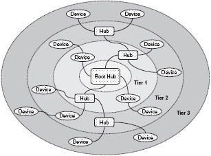
The maximum bandwidth of USB 1.0 was 12 Mbps, but this has since increased to a FireWire matching 480 Mbps with USB 2.0. USB uses a host-centric architecture, with a host controller dealing with the identification and configuration of devices connected either directly to the host or to intermediate hubs (Figure 2).
The USB specification supports both isochronous and asynchronous transfer types over the same connection. Isochronous transfers require guaranteed bandwidth and low latency for applications such as telephony and media streaming, while asynchronous transfers are delay-tolerant and are able to wait for available bandwidth.
USB control protocols are designed specifically to give a low protocol overhead, resulting in highly effective utilisation of the available bandwidth. This available bandwidth is shared among all connected devices and is allocated using “pipes”, with each pipe representing a connection between the host and a single device.
The bandwidth for a pipe is allocated when the pipe is established, and a wide range of different device bit rates and device types can be supported concurrently. For example, digital telephony devices can be concurrently accommodated ranging from 1 “bearer” plus 1 “demand” channel (64 kbps — see ISDN above) up to T1 capacity (1.544 Mbps).
USB employs NRZI (Non Return to Zero Inverted) as a data encoding scheme. In NRZI encoding, a 1-bit is represented by no change in output voltage level and a 0-bit is represented by a change in voltage level.
A string of 0-bits therefore causes the NRZI output to toggle between states on each bit cycle, while a string of 1-bits causes a period with no transitions in the output. NRZI has the advantage of a somewhat improved noise immunity compared with the straight encoding of the input data stream as output voltages.
Physical Layer Technologies — Wireless Networks
The PHY layer technologies that provide the Layer 1 foundation for wireless networks will be described later, where LAN, PAN and MAN technologies and their implementations will be covered in detail. Each wireless PHY technology, from Bluetooth to ZigBee, will be described in terms of a number of key aspects.
- Spectrum - What part of the electromagnetic spectrum is used, what is the overall bandwidth available, how is this segmented into channels? What mechanisms are available to control utilised bandwidth to ensure coexistence with other users of the same spectrum?
- Propagation - What power levels are permitted by regulatory authorities in the spectrum in question? What mechanisms are available to control the transmitted power or propagation pattern to minimise co-channel interference for other users, maximise effective range or utilise spatial diversity to increase throughput?
- Modulation - How is encoded data carried on the physical medium, for example by modulating one or more carriers in phase and/or amplitude, or by modulating pulses in amplitude and/or position?
- Data encoding - How are the raw bits of a data frame coded into symbols for transmission? What functions do these coding mechanisms serve, for example increasing robustness to noise or increasing the efficient use of available bandwidth?
- Media access - How is access to the transmission medium controlled to ensure that the bandwidth available for data transmission is maximised and that contention between users is efficiently resolved? What mechanisms are available to differentiate media access for users with differing service requirements?
The range and significance of the issues vary depending on the type of technology (Ir, RF, Near-field) and its application (PAN, LAN or WAN).