Surveying the RF environment
Conducting a site survey is an important step in planning and designing all but the simplest WLAN. It is important to determine the impact of environmental factors on radio wave propagation in the operating area of the LAN, and also to test for the presence of RF signals that will interfere with WLAN performance.
The objective of the site survey is to gather enough information to plan the number and location of access points to provide the required coverage, in terms of achieving a minimum required data rate over the operating area. There are two types of site survey that can be performed — a noise and interference survey and a propagation and signal strength survey.
Noise and Interference Survey
This survey looks specifically for the presence of radio interference coming from other sources, such as nearby networks, military installations, etc., that could degrade WLAN performance. The main aspects of this type of survey are described below:
- Objective - Assess the noise floor (RF power per unit of bandwidth, dBm/MHz) across the intended bandwidth to be used by the WLAN. Identify the distribution of RF energy within the bandwidth (frequency, continuous or sporadic, peak and average power levels).
- Equipment used - Stand-alone RF spectrum analyser or PC equipped with a wireless interface card and spectrum analysis software
- Survey technique - Site walk-through test prior to access point placement. Extended point measurements should be made at selected locations to identify any intermittent interference sources.
- Application of survey results - Noise floor measurements will be used in the link budget calculation to assess the effective range of an RF link given the hardware specifications (transmit power, receiver sensitivity, antenna gains). Interference results will indicate any limitations on bandwidth usage, such as channels that should be avoided, and in extreme cases may dictate a choice between 2.4 and 5 GHz operation.
Propagation and Signal Strength Survey
A well executed propagation and signal strength survey will help to ensure that network resources are correctly located so that the planned network will not suffer from coverage holes, resulting in areas of poor network performance, and will also ensure that network capacity is properly planned. The main aspects of this type of survey are described below:
- Objective - Identify the coverage pattern, received signal strength and achievable data rate for given access point and client station locations within the WLAN operating area.
- Equipment used - Laptop or handheld PC equipped with wireless interface card and site survey software. Ideally the survey receiver hardware should be identical to the planned client station hardware (same wireless NIC), otherwise allowances will need to be made, for example for differing receiver sensitivity or antenna gain. Combining the survey tool with a GPS navigation module can help in transferring measurements onto site plans.
- Survey technique - Site walk-through test following preliminary access point placement, measuring received signal strength and maximum data rate at each location. If both 2.4 and 5 GHz operation are under consideration, the survey will need to be conducted in each band, as propagation patters will differ widely between these bands.
- Application of survey results - Results will show how the ideal omnidirectional propagation pattern is affected by the operating environment (office partitions, walls, cabinets, lift shafts, etc.). Achievable data rate versus range will dictate the required placement of access points as input to planning the physical hardware layout.
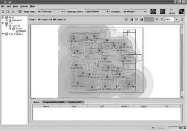
Figure below shows a typical display of propagation and signal strength survey results, which can be used to identify areas where RF propagation is adversely affected by local environmental conditions.
Combined with a similar graphical display of noise floor measurements this will give an indication of potential low SNR areas, which may need to be addressed by adjusting access point or antenna locations or by changing transmitter power settings or antenna gain.
Designing the Physical Architecture
Having built up a picture of the RF environment and gathered data on propagation and signal strength in the operating area, a provisional physical layout of the WLAN can be created. The objective of this stage is to establish a layout of hardware that will ensure complete RF coverage and deliver the required bandwidth to wireless client stations.
Network Physical Layout Design
Planning the physical architecture starts with the floor plans of the operating area and the results of the propagation and signal strength survey, and results in a layout plan detailing:
- the required number of access points
- an optimal antenna type and location
- non-conflicting operating channel
- proper power setting for each access point
Factors influencing physical layout are described below.
- Number - A preliminary count can be established by dividing the overall operating area per access point by the coverage area determined from the propagation and signal strength survey. The area should be taken out to the contour at which the required data rate could be maintained. The effective coverage area of an access point will be reduced if the propagation pattern is far from omnidirectional as a result of nearby obstacles.
- Optimal antenna location - The optimal location for an access point with an omnidirectional antenna will generally be close to the centre of the area to be covered, in a position that maximises line-of-sight to client stations and is clear of obstructions, particularly metal objects such as filing cabinets. An elevated location can be very effective, for example, a ceiling mounted unit.
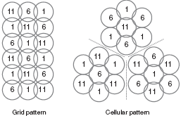
- Operating channel - Any channel that shows significant background or sporadic noise should be avoided. The available non-overlapping channels can then be allocated to access points based on their initial locations. A typical channel allocation pattern for the three non-overlapping channels in the 2.4 GHz band is shown in Figure 2.
- Power setting - In general, the number of access points will be minimised if maximum permitted transmit power is used. Reasons to adopt a lower power setting may be to reduce out of building propagation or to avoid interference with other RF systems. Conversely high power settings may be required to combat local conditions of high RF noise or high path loss.
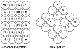
The channel allocation patterns shown in Figure 2 are based on the three non-overlapping channels 1, 6 and 11 in the 2.4 GHz band. However, in those regulatory domains that permit 13 channels in this band (Europe, Japan, etc.) it is possible to operate four access points with minimal frequency overlap on channels 1, 5, 9 and 13, potentially increasing network capacity by one-third.
This would permit the additional channel allocation patterns shown in Figure below.
Early WLAN layouts were often developed on a trial-and-error basis, by temporarily deploying access points, taking signal strength and throughput measurement (essentially repeating a site survey) and then relocating or adding access points to fill in any identified holes in RF coverage.
Planning tools such as Wireless Valley’s “LAN Planner” are available that improve WLAN design by simulation and graphical display of the expected performance of the network. Information such as received signal strength indicator (RSSI), signal to interference ratio (SIR), signal to noise ratio (SNR), throughput and bit error rate (BER) can be displayed on digitised site plans, allowing more accurate planning in complex environments.
Besides automated placement and configuration of network components, these tools can also ease the later stages of implementation by automatically generating bills of materials and maintenance records.
Design and Deployment Using Wireless Switches
Wireless switches not only change the way in which network traffic is routed between stations, but also provide in-built tools that aid the design and later the configuration process, particularly in large-scale WLAN installations. Typically a wireless switch tool kit will include:
- Automatic layout planning for capacity and coverage
- One-click configuration of multiple access points and WLAN switches
- Simple monitoring and operation, from the detection and location of rogue access points to automatic transmitter power adjustment to eliminate coverage gaps and optimise network performance.
Network Bridging — Point-to-point Wireless Links
If the WLAN requirements include linking two separate operating areas, for example providing a link from a WLAN in one building to a wired or wireless LAN in a second, then a point-to-point link will need to be designed.
Since RF propagation is more predictable outdoors than indoors, this will generally be more straightforward than designing indoor layouts as described above. Provided suitable antenna locations can be identified that offer a direct line-of-sight between the locations, a link budget calculation can be performed.
The required combination of transmit power and antenna gain needed to deliver sufficient received signal strength to achieve the desired data rate can be determined, given the link range and intended RF band.


