The topology of a wired network refers to the physical configuration of links between networked devices or nodes, where each node may be a computer, an end-user device such as a printer or scanner, or some other piece of network hardware such as a hub, switch or router.
The building block from which different topologies are constructed is the simple point-to-point wired link between two nodes, shown in Figure 1.
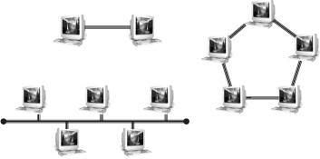
For the ring topology, there are two possible variants depending on whether the inter-node links are simplex (one-way) or duplex (two-way). Repeating this element results in the two simplest topologies for wired networks — bus and ring.
In the simplex case, each inter-node link has a transmitter at one end and a receiver at the other, and messages circulate in one direction around the ring, while in the duplex case each link has both transmitter and receiver (a so-called transceiver) at each end, and messages can circulate in either direction.
Bus and ring topologies are susceptible to single-point failures, where a single broken link can isolate sections of a bus network or halt all traffic in the case of a ring. The step that opens up new possibilities is the introduction of specialised network hardware nodes designed to control the flow of data between other networked devices.
The simplest of these is the passive hub, which is the central connection point for LAN cabling in star and tree topologies, as shown in Figure 2.
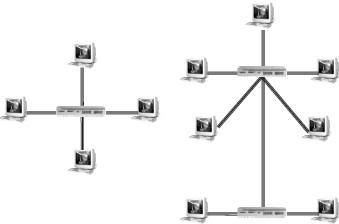
An active hub, also known as a repeater, is a variety of passive hub that also amplifies the data signal to improve signal strength over long network connections. For some PAN technologies, such as USB, star and tree topologies can be built without the need for specialised hardware, because of the daisy-chaining capability of individual devices.
An active or passive hub in a star topology LAN transmits every received data packet to every connected device. Each device checks every packet and decodes those identified by the device’s MAC address. The disadvantage of this arrangement is that the bandwidth of the network is shared among all devices, as shown in Figure 3.
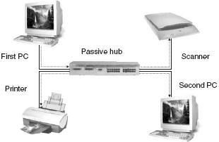
For example, if two PCs are connected through a 10 Mbps passive hub, each will have on average 5 Mbps of bandwidth available to it. If the first PC is transmitting data, the hub relays the data packets on to all other devices in the network. Any other device on the network will have to wait its turn to transmit data.
A switching hub (or simply a switch) overcomes this bandwidth sharing limitation by only transmitting a data packet to the device to which it is addressed. Compared to a non-switching hub, this requires increased memory and processing capability, but results in a significant improvement in network capacity.
The first PC (Figure 4) is transmitting data stream A to the printer and the switch directs these data packets only to the addressed device.
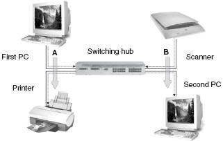
At the same time, the scanner is sending data stream B to the second PC. The switch is able to process both data stream concurrently, so that the full network bandwidth is available to every device.
Wireless Network Topologies
Point to Point Connections
The simple point to point connection shown in Figure 1 is probably more common in wireless than in wired networks, since it can be found in a wide variety of different wireless situations, such as:
- peer-to-peer or ad-hoc Wi-Fi connections
- wireless MAN back-haul provision
- LAN wireless bridging
- Bluetooth
- IrDA
Star Topologies in Wireless Networks
In wireless networks the node at the centre of a star topology (Figure 5), whether it is a WiMAX base station, Wi-Fi access point, Bluetooth Master device or a ZigBee PAN coordinator, plays a similar role to the hub in a wired network.
The different wireless networking technologies require and enable a wide range of different functions to be performed by these central control nodes. The fundamentally different nature of the wireless medium means that the distinction between switching and non-switching hubs is generally not relevant for control nodes in wireless networks, since there is no direct wireless equivalent of a separate wire to each device.
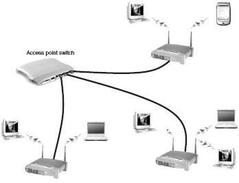
The wireless LAN switch or controller (Figure 6) is a wired network device that switches data to the access point that is serving the addressed destination station of each packet.
The exception to this general rule arises when base stations or access point devices are able to spatially separate individual stations or groups of stations using sector or array antennas. Figure 7 shows a wireless MAN example, with a switch serving four base station transmitters each using a 90 sector antenna.
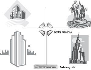
With this configuration, the overall wireless MAN throughput is multiplied by the number of transmitters, similar to the case of the wired switching hub shown in Figure 4.
In the wireless LAN case, a similar spatial separation can be achieved using a new class of device called an access point array, which combines a wireless LAN controller with an array of sector antennas to multiply network capacity.
The general technique of multiplying network throughput by addressing separate spatial zones or propagation paths is known as space division multiplexing, and finds its most remarkable application in MIMO radio.
Mesh Networks
Mesh networks, also known as mobile ad hoc networks (MANETs), are local or metropolitan area networks in which nodes are mobile and communicate directly with adjacent nodes without the need for central controlling devices.
The topology of a mesh, shown generically in Figure 8, can be constantly changing, as nodes enter and leave the network, and data packets are forwarded from node-to-node towards their destination in a process called hopping.
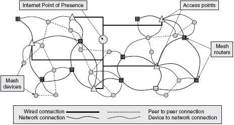
The data routing function is distributed throughout the entire mesh rather than being under the control of one or more dedicated devices. This is similar to the way that data travels around the Internet, with a packet hopping from one device to another until it reaches its destination, although in mesh networks, the routing capabilities are included in every node rather than just in dedicated routers.
This dynamic routing capability requires each device to communicate its routing information to every device it connects with, and to update this as nodes move within, join and leave the mesh. This distributed control and continuous reconfiguration allows for rapid re-routing around overloaded, unreliable or broken paths, allowing mesh networks to be self-healing and very reliable, provided that the density of nodes is sufficiently high to allow alternative paths.
A key challenge in the design of the routing protocol is to achieve this continuous re-configuration capability with a manageable overhead in terms of data bandwidth taken up by routing information messages. One approach to this problem, the biologically inspired AntHocNet.
The multiplicity of paths in a mesh network has a similar impact on total network throughput as the multiple paths shown in Figures 4 and 7 for the case of wired network switches and sectorised wireless networks.
Mesh network capacity will grow as the number of nodes, and therefore the number of usable alternative paths, grow, so that capacity can be increased simply by adding more nodes to the mesh. As well as the problem of efficiently gathering and updating routing information, mesh networks face several additional technical challenges such as:
- Wireless link reliability — a packet error rate that may be tolerable over a single hop in an hub and spokes configuration will quickly compound over multiple hops, limiting the size to which a mesh can grow and remain effective.
- Seamless roaming — seamless connection and reconnection of moving nodes has not been a requirement in most wireless network standards, although 802.11 Task Groups TGr and TGs are addressing this.
- Security — how to authenticate users in a network with no stable infrastructure?
From a practical standpoint, the self-configuring, self-optimising and self-healing characteristics of mesh networks eliminate many of the management and maintenance tasks associated with large-scale wireless network deployments.
ZigBee is one standard which explicitly supports mesh networks and the IEEE 802.11 Task Group TGs is in the process of developing a standard which addresses WLAN mesh networks. Two industry bodies have already been established to promote 802.11s mesh proposals, the Wi-Mesh Alliance and SEEMesh (Simple, Efficient and Extensible Mesh).